Ask technical questions, discuss hifi, show pics of your gear: Join us on


Shopping Cart |

Accepted..
Cookie information:
We only use a session cookie. This cookie stores your shopping basket while your are navigating on our pages. The moment you leave NewClassD.com, the session cookie is destroyed, and erased. | | | Neutron Star Generic Instructions
Click
Before you order.
| 1.. | Decide whether you want a tuning shop to perform the installation or you want to do it yourself. |
| 2.. | Disconnect the mains chord. CAUTION Risk of electric shock! |
| 3.. | Open your player. |
| 4.. | Identify the crystal. It should look like one of these: |
| |
The marking should correspond to one of the 'audio' frequencies on the frequency list:
8.467200 MHz
11.289600 MHz
12.288000 MHz
16.934400 MHz
22.579200 MHz
24.576000 MHz
27.000000 MHz
33.868800 MHz
45.158400 MHz
These frequencies are all a multiplum of 44.1 or 48 kHz sampling frequency. For example 11.2996 MHz is 256 x 44.1 kHz.
The marking may only be some of the digits, for example 16.934400 MHz, may be marked on the crystal simply as 16.9. But if you find a crystal marked with 4.00 or 10.700, you are looking at the wrong crystal. A player can have several crystal for various purposes.
Also some players have a digital input, in this case, make sure you are not looking at the crystal from the digital input decoder. It makes no sense to upgrade that one with a clock, as it is turned off, once the chip has locked onto the signal. |
| 5.. | Note the correct frequency and DAC or other chip that the crystal is directly connected to. |
| 6.. | Assemble your player again. |
| 7.. | Order the correct Neutron Star Reference Clock. |
| 8.. | Find the datasheet of the chip, that your crystal is directly connected to. [Here] is a good datasheet search machine. |
The Installation.
| 1.. | Disconnect the mains power. |
| 2.. | Open your player. |
| 3.. | Connect power, and turn on the power. CAUTION Risk of electric shock! |
| 4.. | If you were unable to find the correct datasheet of the chip your crystal was connected to, use this simple trick:
Place a CD in the player, start playing at low volume.
Touch each side of the crystal with a small screw driver, to determine which one makes the sound stop or scramble.
The one side of the crystal which is more sensitive, is going to be your injection point for the clock signal from Neutron Star.
Mark it up with a pen.
4b.. An alternative method to find the injection point is this: Remove the xtal. Connect the clock to any of the two xtal pins through a 1k resistor, and of course the
shield of the coax cable to GND. (See pt. 14 below) Then if the machine will turn on, and function normally, then you have the right injection point, in the xtal pin you just used.
If it does not start up and function normally, then try the other xtal pin.
When you found the right pin, mark it up with a permanent marker.
If you were able to find the datasheet, find the two pins of the chip, where the crsytal is connected. They will most likely be demoninated XI and XO in the datasheet. Or in case of a logic chip, like 74HC04 or alike, you will be able to read which pin is input and which one is output.
You will use the input pin, or XI as injection point for the clock signal from NS.
NOTE: Never connect the signal from the clock to one xtal pin, and then the GND to the other xtal pin. It may seem obvious, but we see this mistake all the time. :-) |
| 5.. | Now determine whether your player runs on 3V or 5V. This is easy.
Measure the other terminal of the crystal with your multimeter. If it shows around 1.4V, your system runs on 3V. If it reads 2.4V it's 5V.
Most aged players run on 5V, while newer players especially DVD players run on 3V.
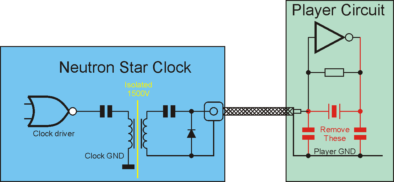
Click!
This is the typical circuit, which will automaticly align itself to the right DC level.
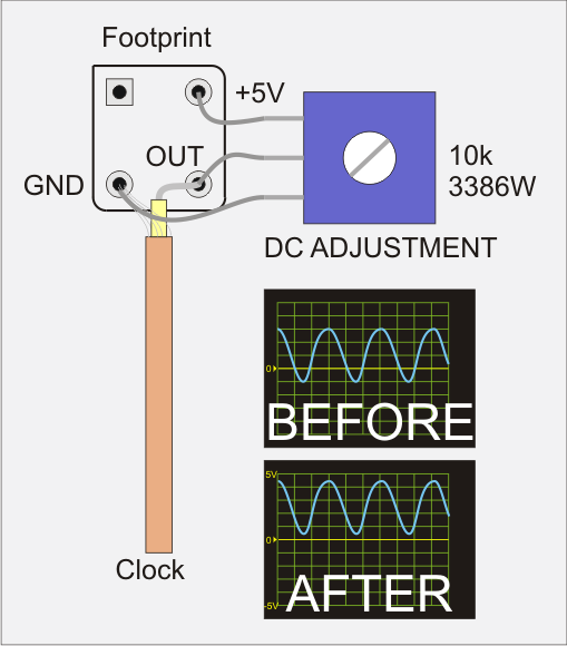
Click!
In case the clock signal ports directly to a gate with no DC alignment, you should use a trimmer to make sure the DC level is correct. This is typically the case if the factory clock is a metal can oscillator (..and not a discrete crystal unit).
Click!
In case your player has a crystal oscillator rather than a crystal, simply measure the voltage between the corner pins, it is most likely 5V, in which case it's a 5V system. |
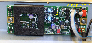
| 6.. | Set the 5V solder bubble on Neutron Star, in case it's a 5V system. It's located right between the two blue LED's. |
| 7.. | Use a multimeter to identify a good power source of 10 - 15V DC, with ground potential the same as the enclosure. You can check this by placing your test wires between the enclosure, and the terminal you want to use as GND for Neutron Star. It must show close to zero Volts.
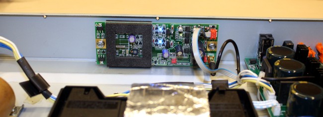
The best power source is on a large can electrolytic capacitor, such as the dark green ones you see on the photo above. Just make sure the voltage on the cap is between 10 and 15V.
If you cannot find an appropriate power source, we recommend you use a separate power supply module of 12-15V DC 200mA or more. Preferably with low noise regulation. |
| 8.. | Turn the player off again, and remove the power cord. |
| 9.. | Find out where the Neutron Star module will fit inside your player. Mark up the holes for the two M4 screws, and drill them. Mount the module. |
| 10.. | Fit the signal cable on the clock module, lead it towards the crystal on the CD player's motherboard, and cut the cable in a fitting length. |
| 11.. | Remove screws holding down the PCB where the crystal is mounted. (Unless your crystal was of the SMD - surface mounted - type). Careful not to stress the wires and connectors. You may have to remove some of them, to get to the other side of the circuit board. In this case write down which wire goes into which connector. Or take a good picture of the whole thing before disassembling it. This way it's easy to assemble again. |
| 12.. | Unsolder the crystal. |
| 13.. | Remove insulation from the clock signal cable, and solder the inner wire onto the terminal of the crystal you marked up as injection point. |
| 14.. | Solder the outer wire (GND) onto GND. NOT onto the other crystal terminal. |
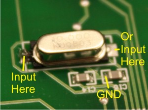
Click
You can identify a good GND at the point where the two capacitors on the crystal meet.
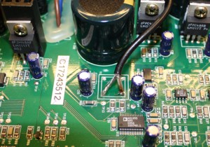
Click
Or in case of a crystal oscillator, simply use these terminals of the 4 pin can, for GND and injection.
Notes on installation:
GND Potential.
|
The Neutron Star is GND connected in the screws, so the GND potential of the power supply wire (going into the orange power plug) must be 0V compared to the chassis potential. The D-Clock was not GND connected, so D-Clock would work correctly
| |
even with GND potential difference. If it's not possible to obtain the same potential, we recommend using isolating plastic spacers (not included). Then the Neutron Star will work correctly with different GND potentials.
|
|
| 15.. | Solder the Neutron Star power cable onto the electrolytic capacitor you identified as a good power source. The line marked wire of the cable is GND. |
| 16.. | Asseble the player again, with all the screws in position to hold down the motherboard. And remember to fit the player's connectors as well. |
| 17.. | Make sure both connectors are fitted correctly on the Neutron Star. |
| 18.. | Connect power to the player, and turn it on. |
| 19.. | Observe the two blue LED's turn on, to show that power is present. |
| 20.. | Make a test run with low volume, to make sure the player has accepted the new clock signal. |
| 21.. | If the red LED light up, it means your power source is contaminated with noise or ripple. The clock will still work correctly, but you may get some improvement if you use a good power supply instead. |
| 22.. | After a couple of minutes the green LED will turn on, to indicate that the Neutron Star has reached it's correct operating temperature of 37 degrees Celcius. |
| 23.. | Assemble the enclosure again. |
That's It!
Congratulations, you have upgraded your player. Best sound performance will reveal itself after 1-2 weeks of operation.
Should you experience any problems with the installation, please contact me by e-mail: sales@newclassd.com.
Enjoy!
|
|
|